Overview
Most robotics pipelines work flawlessly until they leave simulation.
This project focused on a harder and more practical objective: making a robotic sensing system reliable in real-world conditions. Using an AgileX Piper arm, we built a waypoint-based sensing pipeline that could move through predefined poses, capture measurements, and keep operating safely even when hardware behavior differed from simulation.
For robotics teams, this is where many promising prototypes break down. A pipeline that looks complete in simulation still needs control redesign, hardware validation, and failure handling before it becomes useful in production. This work was about closing that gap.
The result was not just a working demo, but a more dependable sensing workflow designed for long-duration execution on real hardware and a strong foundation for inspection, measurement, and structured data-collection applications.
Figure 1: End-to-end sensing workflow on the AgileX Piper arm during waypoint-based data collection.
Problem Statement
The core task looked simple on paper:
- Attach a sensor to the robotic arm
- Move the arm through predefined spatial waypoints
- Record readings at each location
From an engineering perspective, the real requirement was broader: build a sensing workflow that could execute repeatably on hardware, tolerate real-world imperfections, and remain stable long enough to support practical deployment.
This type of workflow is relevant to:
- Industrial inspection
- Environmental sensing
- Repeatable measurement collection
- Sensor validation and data-acquisition pipelines
System Setup
We designed the system with a simulation-first workflow so that trajectory definition and validation could happen before deployment on hardware.
The architecture included:
- AgileX Piper arm as the sensing platform
- Sensor mounted to the end-effector
- Cartesian waypoint definition for target sensing poses
- Inverse kinematics based trajectory generation during early development
- Calibration offsets applied before real-robot execution
This architecture let us move quickly during development, but it also exposed the core deployment challenge: simulation was helpful for iteration speed, yet insufficient as the final source of truth for reliable execution.
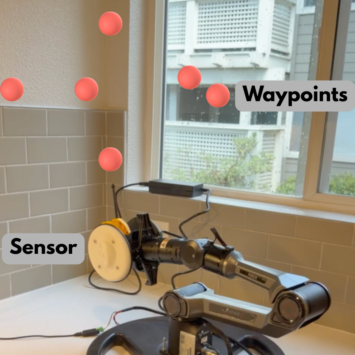 Figure 2: Sensor-integrated Piper arm setup used for structured sensing trials.
Approach: From Simulation to Real Robot
The first phase of the project was validating the sensing workflow in simulation. The robot successfully traversed the required waypoints, and the motion pipeline appeared stable.
Once those trajectories were transferred to hardware, several failures appeared immediately. Motion quality degraded, some target poses became unreliable, and assumptions that held in simulation no longer matched the real robot.
This project became a useful example of the simulation-to-real gap in robotics: the system was logically correct, but not yet operationally reliable.
That gap is often the difference between an internal demo and a deployable robotics system. Closing it required changes across controls, hardware understanding, and operational safeguards rather than a single isolated fix.
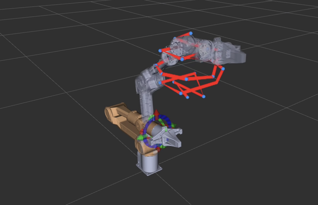 Figure 3: Simulation validation of waypoint traversal before deployment on hardware.
Challenge 1: Simulation-to-Real Execution Gap
Problem
The robot could not consistently reach target sensing poses when using the original IK-driven control strategy on hardware.
In practice, the end-effector missed targets, motion quality became inconsistent, and pose execution was less stable than expected from simulation.
 Figure 4: Early hardware trials showing pose inconsistency under IK-driven execution.
Root Cause
Several small mismatches compounded into larger real-world errors:
- Simulation models did not perfectly match hardware behavior
- Small modeling or calibration errors produced large end-effector deviations
- IK-based control proved brittle under real physical constraints
Solution
To improve execution reliability, we changed the control strategy:
- Switched from IK-centric execution to joint-space position control
- Relaxed orientation constraints during transit motions
- Applied orientation correction only at the actual sensing points
This reduced sensitivity during movement while preserving pose quality where measurements actually mattered.
Result
- Reachability became significantly more reliable
- Motion instability was reduced
- Execution time improved due to fewer unstable corrections
- The sensing process became more practical for repeatable hardware use
Challenge 2: Joint-Limit Mismatch on Hardware
Problem
Even after the control changes, the robot still showed motion inconsistencies that did not fully match the expected model.
Discovery
A critical mismatch was found between documentation and hardware behavior:
- Documented Joint 5 limits:
-70 degto70 deg - Observed hardware limits:
0 degto180 deg
This discrepancy directly affected planning validity.
Impact
- Motion plans were being generated with invalid assumptions
- IK failures persisted for poses that should have been feasible
- Some targets became effectively unreachable under the incorrect model
Fix
We resolved the issue by aligning the software model with the real robot:
- Reverse-engineered the actual joint behavior from hardware tests
- Updated the control logic with corrected joint limits
- Recomputed trajectories using the validated limits
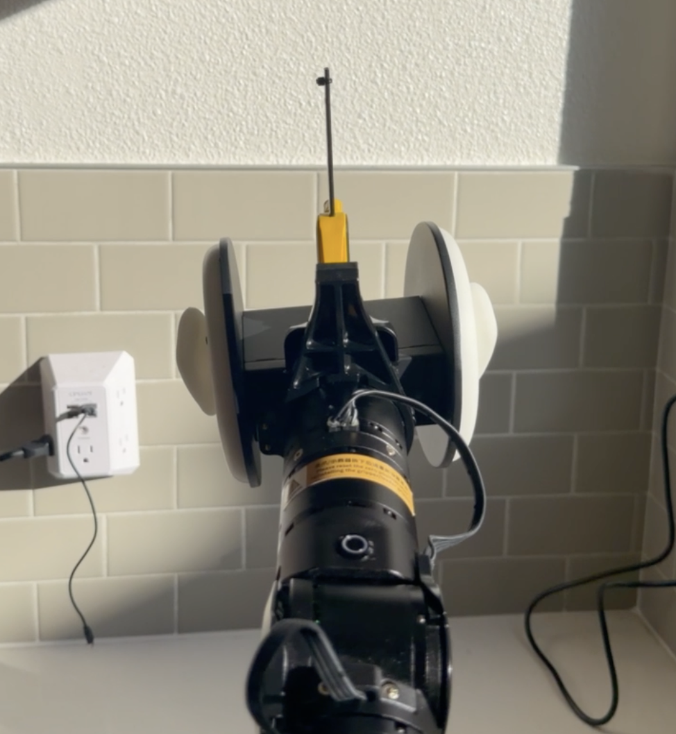 Figure 5: Robot pose with joint limit mismatch.
Result
- Motion behavior became consistent
- Planning failures caused by invalid limits were eliminated
- The planning stack better reflected the physical robot rather than nominal documentation
Challenge 3: Oscillation and Thermal Shutdown Under Payload
Symptoms
During repeated operation, the robot began to show:
- Oscillations when stopping
- Unexpected motor shutdowns in the middle of execution
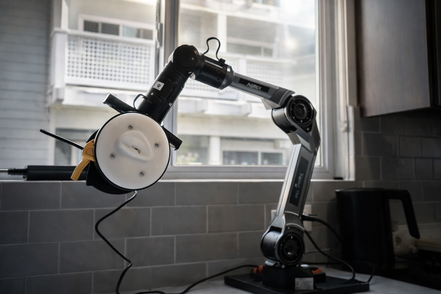 Figure 6: Payload-induced oscillation and motor shutdown observed during repeated trials (AI used to enhance image).
Root Cause
The underlying issue was thermal stress caused by payload-induced torque.
Even though the payload was only around 1.5 kg, real operating conditions amplified the load:
- The sensor mounting arrangement increased torque on the arm
- Motion dynamics created higher effective stress than static weight alone
- Motors entered thermal protection during demanding operation
This was an important reminder that payload capacity on paper does not automatically translate to stable long-duration behavior in practice.
For real deployments, this matters directly. If a sensing or inspection robot cannot maintain stable runtime under its actual payload and mounting configuration, the system is not yet operationally useful.
Hardware Debugging
To validate the thermal-load hypothesis, we tested multiple payload configurations and observed the effect on stability.
This debugging process included:
- Trying lighter payload setups
- Comparing motion quality across configurations
- Identifying safer operating thresholds for repeatable execution
Those tests confirmed that the issue was not purely software-related. Mechanical loading and system dynamics were central to the failure mode.
This hardware iteration was important operationally as well: after the mounting and reliability changes, stable runtime improved from roughly 2 minutes to 8 minutes in repeatable execution.
That improvement changed the project from a short-lived proof of concept into a much more credible sensing platform for real-world task cycles.
Reliability Engineering: Defensive Control Layer
Getting the robot to work once was not enough. The real goal was to make it recover gracefully when instability appeared.
We added a defensive control layer designed around operational reliability rather than ideal conditions.
The system monitored robot behavior and detected signs of overload or unstable execution. When a fault condition appeared, the robot could:
- Return to a safe home position
- Pause to allow cooling
- Resume the sensing task automatically
This changed the system from a fragile demo into a more resilient robotic workflow.
From a portfolio and client-delivery perspective, this layer is one of the most important parts of the project. Reliable robotics systems are defined not only by nominal behavior, but by how they respond when hardware stress, thermal limits, or execution faults appear during operation.
Why This Matters
In real deployments:
- Hardware performance changes over time
- Payload and environmental conditions vary
- Failures are inevitable
Reliable robotic systems need to handle those events deliberately, not just hope they never happen.
Final Outcome
After the control redesign, joint-limit correction, payload debugging, and recovery-layer implementation, the system reached a much more dependable operating state.
The final pipeline delivered:
- Stable waypoint traversal
- Reliable sensing execution
- No unexpected shutdowns during validated operation
- Safer long-duration behavior on real hardware
More importantly, the project demonstrated a repeatable engineering process for turning a simulation-validated manipulation workflow into a more deployment-ready sensing system.
Key Learnings
1. Simulation Is Not Enough
A pipeline that works in simulation still needs control flexibility and calibration awareness before it becomes reliable on hardware.
2. Documentation Must Be Verified
Hardware limits and behavior should be validated directly. Incorrect assumptions at this level can invalidate the entire planning stack.
3. Payload Is More Than Weight
Torque, mounting geometry, and motion dynamics often matter more than the nominal payload number alone.
4. Reliability Must Be Engineered
Fallback behavior, monitoring, and recovery logic are not optional extras. They are part of making a robotic system deployable.
Why This Matters for Robotics Projects
Teams building inspection systems, manipulation platforms, or autonomous sensing pipelines often encounter the same issues:
- IK failures on hardware
- Mismatch between documentation and real behavior
- Overheating, instability, or degraded motion quality
These are not edge cases. They are standard real-world robotics challenges, and solving them requires both software and hardware awareness.
For companies moving from prototype to pilot deployment, this is often where engineering effort has the highest leverage. Small corrections in control architecture, hardware assumptions, and recovery behavior can determine whether a system remains a lab demo or becomes a reliable operational tool.
Closing Note
This project showed how a straightforward sensing task becomes a meaningful engineering problem once it reaches real hardware.
By redesigning the control strategy, validating real joint behavior, and adding a defensive recovery layer, we turned a brittle simulation-success story into a more reliable robotic sensing system on the AgileX Piper arm.
This is the kind of work Kodo Robotics focuses on: helping teams bridge simulation-to-real deployment, harden manipulation and sensing workflows, and build robotic systems that keep working outside ideal conditions.